Software Engineer and Maker. I have a passion for innovation and love to tinker with electronics. When I am not programming or soldering, I blog on platis.solutions about my latest creations.
In this tutorial I will walk you through the steps that were taken in order to build an Android autonomous vehicle. The related software, that runs in said platform can be found on GitHub in the /Examples/AndroidCar folder of the AndroidCar library. Before proceeding to the construction details, let me provide a brief background on the reasoning behind it.
In my project, I prioritized the following considerations:
Modularity: The ability to divide a big problem into smaller ones. In order to achieve this, the vehicle is divided into three compartments or levels.
Minimum visible cabling: The fewer cables, the lower the probability of accidents (short circuits, broken connections etc).
Deployability: By adopting a modular design, the ability to easily deploy the vehicle is increased.
Maintainability: Make the system easy to modify, improve, or repair.
Last but not least, I will not be going into platform specific details, such as how to mount the speed encoder or how to calibrate the electronic speed controller. Instead, I’ll focus on the development and features of what I consider to be the first Android autonomous vehicle. It was created by Team Pegasus during the Spring of 2015 during the DIT168 course at the University of Gothenburg. The rest of the Team Pegasus who worked on this project are Yilmaz Caglar, Aurélien Hontabat, David Jensen, Simeon Ivanov, Ibtissam Karouach, Jiaxin Li, and Petroula Theodoridou.
We used an R/C car from a brand called HSP Racing. Anything with similar chassis should also work.
Arduino Mega
The Arduino Mega controls the various sensors and the motors. It does not have a decision making role and just relays the data to the Android phone.
Bluetooth module (HC-05)
This inexpensive Bluetooth module allows the Arduino Mega to easily communicate with the mobile phone. Whatever is being sent via a serial connection to the Bluetooth module is being transmitted wirelessly to whichever device is currently connected to the Bluetooth module. On the HC-05, there is also a pin that indicates whether there is an active connection at the moment, which we utilize in order to fetch and transmit data from the Arduino, only when that is necessary.
Electronic Speed Controller
The electronic speed controller is the component that drives the motors according to a PWM signal it receives from the Arduino. It is connected to a 7.2V battery.
Servo motor
The Servo motor, which is controlled by the Arduino via a PWM signal, determines the angle of the vehicle’s front wheels. It is connected to the battery and not the Arduino 5V output for safety reasons, since it can draw a large load of current.
Ultrasonic distance sensors (HC-SR04) (3)
The ultrasonic sensors calculate distance by transmitting an ultrasonic wave pulse and measuring how much time it took to return, after reflecting on an object. Each sensor is connected to two common (digital) Arduino pins.
SHARP infrared sensors (SHARP GP2D120) (3)
The infrared sensors work in a similar manner to the ultrasonic ones. Depending on the distance of the object that they face, they return the equivalent amount of voltage. Each of them is connected to one analog pin on the Arduino. Keep in mind that the specific sensors can reliably measure distances between 4 and 25 centimeters.
The speed encoder is attached to a wheel and allows us to calculate how much distance it has traveled. Having decorated the inside of the wheel with black stripes, the sensor changes its output state whenever it detects a black surface. Therefore, by counting how many state changes have taken place and knowing how much the wheel travels while turning, we can estimate a pulses/distance ratio. The encoder is attached to an interrupt on the Arduino.
Α component that provides feedback on the movement of the car in the three dimensional space. It is consisted of a microcontroller (ATmega328P), an accelerometer, a gyroscope, and a magnetometer. Due to magnetic interference from the motors, its measurements are not very reliable, however that could be improved with filtering through software. We currently do not utilize its readings.
Gyroscope (L3G4200D)
The gyroscope is utilized in order to calculate the angular displacement of the vehicle, or in our case the yaw. This is particularly helpful for parking but could also be used in order to create a map of the path that we have travelled.
Infrared arrays (2)
The infrared arrays are consisted of three infrared sensors each, that return a HIGH signal if they detect a white surface. We use them in order to detect when the vehicle has driven over the middle dashed street line, in order to improve the overtaking performance and accuracy. The four signals (two from each infrared array) are combined in OR gates and the two outputs are attached to interrupts on the Arduino.
The OR gate IC is soldered into a small section of perfboard along with male headers for easy wiring. The OR gates receive signals from the infrared arrays in order to decrease the number of total inputs to the Arduino board. Particularly, from the infrared arrays we receive four signals in total (two from each). In the current setup, we combine the two signals for each array and if at least one of them is HIGH, we forward that signal to the Arduino. The two resulting outputs of the OR gate chip are triggering interrupts on the Arduino to instantly sense if the car has crossed a street line and from which side this occurred.
R/C receiver (Optional but very useful)
We have connected the car’s default R/C receiver to the Arduino in order to retain the control of the car using the R/C controller in case of an emergency. This has proved particularly valuable when it comes to testing the autonomous functions of the car, for obvious safety reasons. The R/C receiver usually has three channels. A control signal that defines whether the remote controller is on or off, one for the motors, and another for the steering wheel. For example, in our vehicle, whenever the remote controller is turned on.
LEDs, ATtiny85, resistors, transistors (Optional)
The above components are needed for an LED driver board. It blinks the equivalent LEDs, depending on whether the car is moving, turning, or is stopped.
In the above schematic you can see how the various connections are made. More importantly, I’ve highlighted how I’ve visualized the different compartments.
For example, the compartment at the top of the car includes the various distance sensors and the LED driver board. The middle compartment is primarily composed of components located on a black plastic sheet that I’ve fitted on the vehicle. These are the Arduino Mega, the Bluetooth module, the R/C override receiver, the connection terminals (not depicted in the schema), the OR gates, the gyroscope, and the 9DOF IMU.
Another way to visualize the sensor wiring of the autonomous Android car.
The Bluetooth module and the 9DOF IMU could be considered members of the bottom compartment, since they are attached directly to the chassis. But because they are easily accessible and not directly under the middle layer, they are not grouped with the components of the lower compartment.
Finally, the least accessible compartment (for a good reason), is composed of components that are mounted on the vehicle’s chassis, such as the battery, the motors, the ESC, the speed encoder and infrared arrays. I deliberately designed all of these compartments so that there are no connections between non adjacent layers. By doing this, the circuitry is easier to modify, repair, and deploy.
The bottom compartment consists of components that you scarcely need to fiddle with after the initial setup. These include the DC motor, the ESC, the Servo motor, the speed encoder, and the infrared arrays. It is also a good practice to add an on/off switch between the battery and the rest of the components.
The infrared arrays allow the car to detect when it crosses the middle dashed street line, improving the overtaking procedure.The speed encoder changes its state depending on whether the infrared beam it emits is reflected back to it. The black surfaces do not reflect the beam back. Notice the stripes of black tape on the inside of the wheel.
For the middle compartment I positioned components on a plastic sheet that I cut to fit the dimensions of the car. Four holes were drilled in the sheet, which allows you to pass cables underneath it. The Arduino Mega, Bluetooth module, R/C override receiver, connection terminals, the OR gates, the gyroscope, and the 9DOF IMU are screwed or glued onto the sheet, which is itself screwed on top of the chassis. Luckily, the vehicle had available screw slots on the chassis to make things easy.
From right to left the following components are visible: The Bluetooth module, the Arduino Mega, the gyroscope, the connection terminal, the OR gates, and the 9DOF IMU. A keen eye might also spot a barebone ATmega328P microcontroller board, however it is for an experimental feature that is not completely integrated yet.The Bluetooth HC-05 moduleThe connection terminal. Includes a 5v voltage regulator, ground pins, as well as a communication bus towards the top compartment. Connections among components of the same compartment are conducted non-transparently if possible, passing the cables under the plastic sheet.The OR gates that receive input from the infrared arrays and their output goes to the Arduino.The communication bus between the middle and the top compartment. Two lines for power and ground. The rest are for sensor data and the serial connection to the LED driver board.
The top compartment is mounted on the inside of the R/C car’s body shell. On it, I’ve mounted the various distance sensors and the LED driver board. This compartment is connected to the middle level solely through the communication bus, which helps to keep wiring relatively clean.
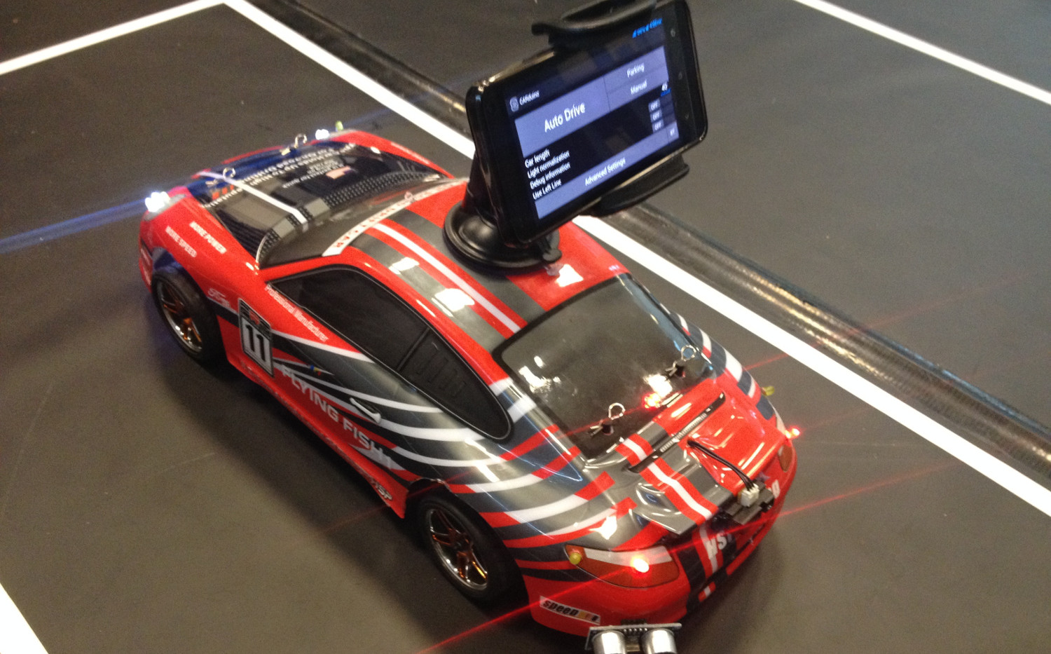
The Android device that interprets the sensor data and analyzes the camera feed is mounted on the outside of the shell using a common phone holder.
The top compartment layout, where the location of the various distance sensors, the LED driver board, and the various status lights are depicted. The orange lights are the blinkers, the red ones indicate when the car is stopped, and the blue one on the top lights up when we override the vehicle’s controls via the R/C controller.The two ultrasonic sensors in the front. The LED lights behind them only serve aesthetic purposes and are constantly on.The ultrasonic sensors are mounted (with the help of hot glue) by making a hole in the encasement, allowing their pins to pass through.The infrared distance sensors that are found on the right side of the vehicle are used to detect parking gaps, as well as to determine whether an obstacle on the street has been overtaken.The LED driver board receives commands from the Arduino Mega’s serial connection and triggers the various transistors accordingly. The ATtiny85 was used because it can connect over UART (through SoftwareSerial) and has just enough pins for the job. Commercial LED Driver boards are an alternative that may save you some trouble.An overview of the top compartment. On paper it looked simple, however many connections have to be made. I suggest gluing cables on the shell in order to avoid getting them tangled with cables in the middle compartment.
The assembled car is controlled using an Android application that communicates over Bluetooth. The app talks to the on-board microcontroller, driving the motors and parsing data from the sensors. Petroula Theodoridou should get most of the credit for the app’s intuitive graphical interface and Bluetooth connectivity..
The Android application, which we named CARduino, successfully runs on Jelly Bean, KitKat, and Lollipop, and was tested on the following phones: JiaYu G4S, XiaoMi Mi3, and OnePlus One.
You can try the different features (check the various branches) in the OpenDaVinci testing environment using the resources found in this repository. It includes an image of the OpenDaVinci environment, with our image processor and driving logic features (parking, overtaking, lane following). Just compile and run.
Software Engineer and Maker. I have a passion for innovation and love to tinker with electronics. When I am not programming or soldering, I blog on platis.solutions about my latest creations.
When you buy through links on our site, we may earn an affiliate commission.
Our websites use cookies to improve your browsing experience. Some of these are essential for the basic functionalities of our websites. In addition, we use third-party cookies to help us analyze and understand usage. These will be stored in your browser only with your consent and you have the option to opt-out. Your choice here will be recorded for all Make.co Websites.
Allow Non-Necessary Cookies
Escape to an island of imagination + innovation as Maker Faire Bay Area returns for its 15th iteration!
Buy Tickets today! SAVE 15% and lock-in your preferred date(s).